Building a soldering station - step 1
When I first got started with IoT a couple of years back, I was fiddling at a very high level with the .NET Gadgeteer platform. Everything where finished modules with fixed wires with connectors on them that you just connected - voila; write some code and you had a fairly powerful device with a bunch of capabilities through the modules that exist for it. After going deeper in understanding and started working with the ESP8266 I got back into soldering again. Its been years since I’ve been there. As part of this, I went out and bought the things I didn’t already have; among this a pair of helping hands:
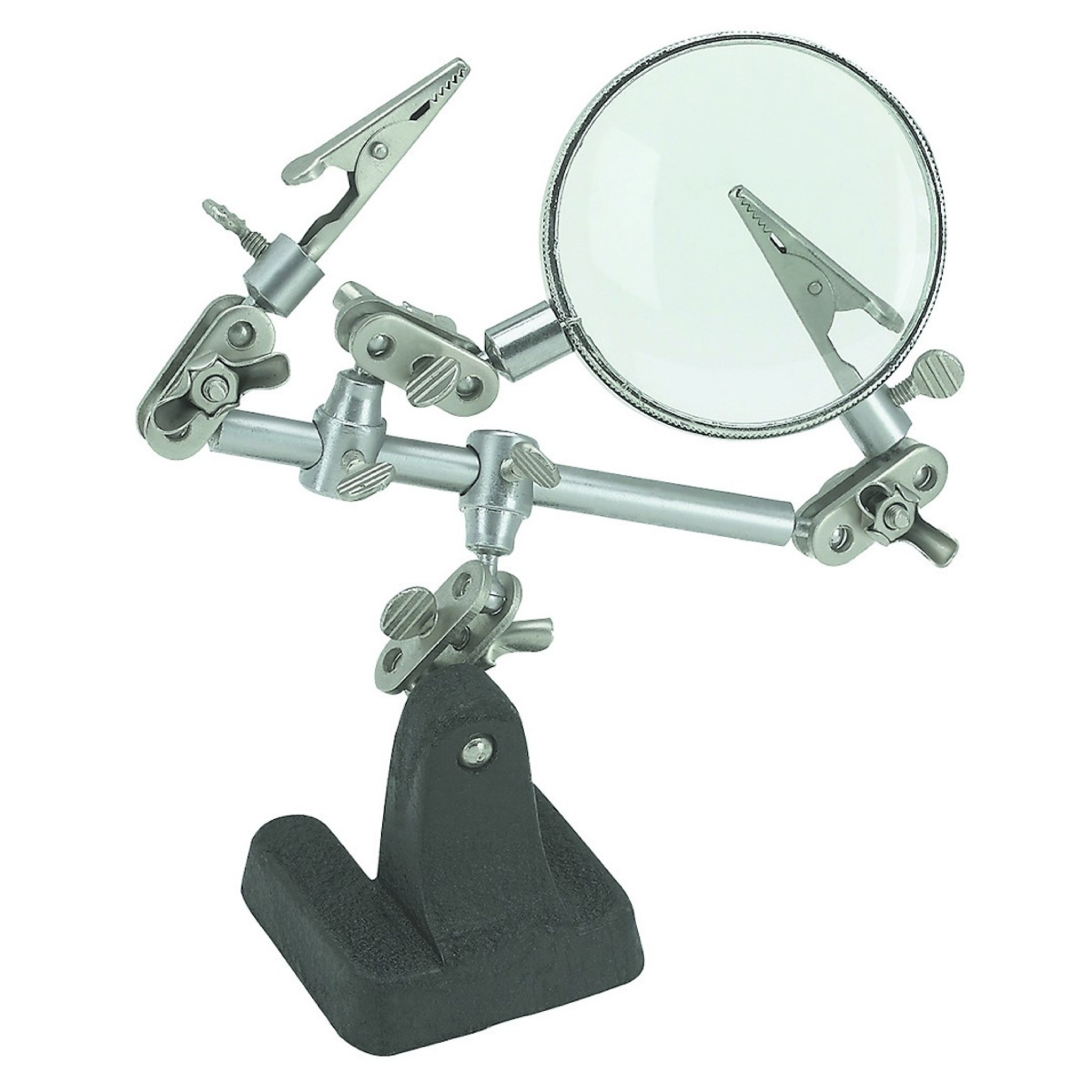
These just turned out to bee way too much of a hassle to use. Couldn’t really get a good stabile soldering station out of it and the helping hands ended up not being helpful at all.
I decided to research what was out there and couldn’t really find something that was affordable enough IMO. Being a hobby, I don’t want to flesh out too much cash on it.
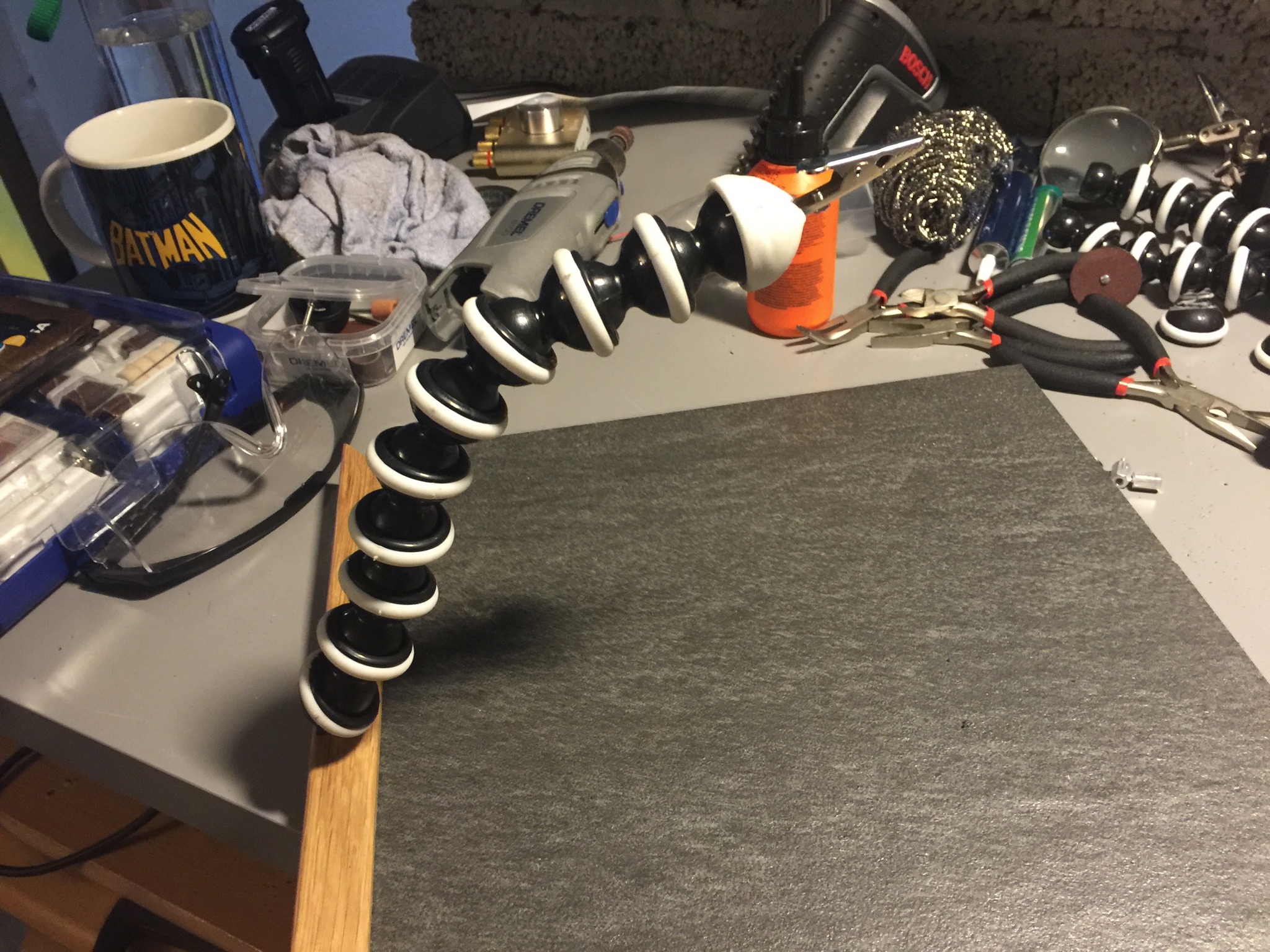
After a bit of research I came across quite a few DIY projects and started planning out my own version, inspired by these. The ones I found the most interesting was the ones based on the gorillapod style camera tripod. The reason I found this the most interesting is that I wanted to have some really sturdy legs - and these are perfect IMO for the job. Anyways, the ones I got were these. With regular crocodile clips
The build
The first thing I did was to disassemble the tripod completely. You can simple pull the legs off by hand with a little force. I peeled off the base - it was glued to the end joint of the legs. With this, I ended up with the following
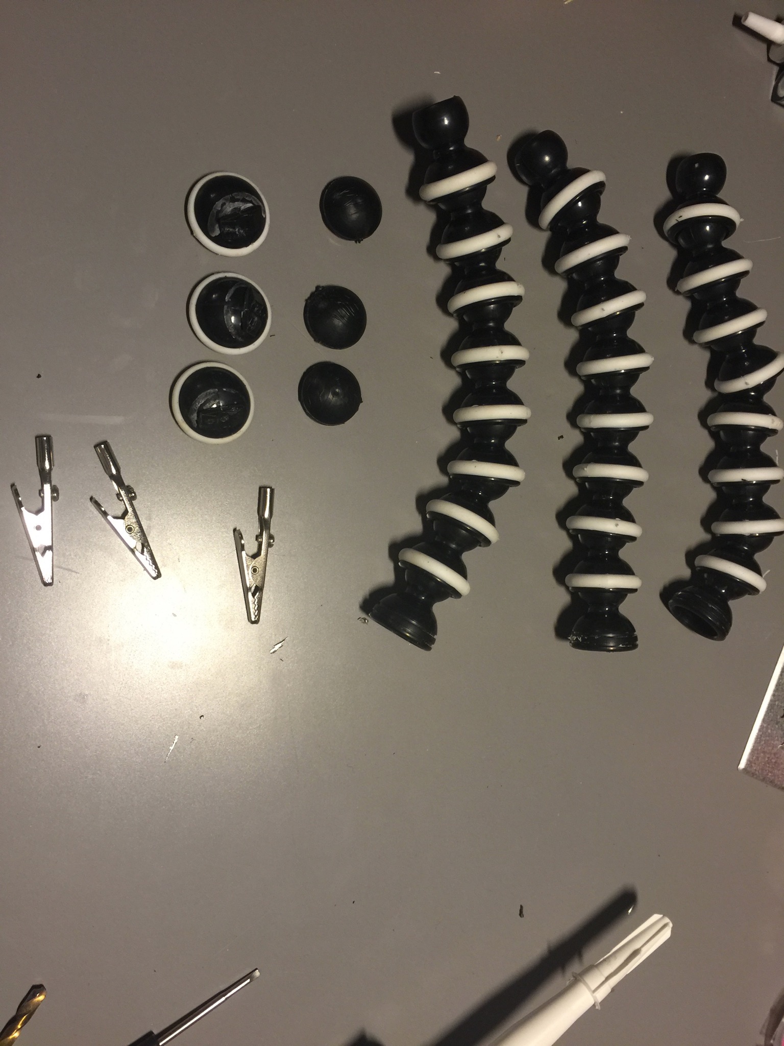
The next thing I did was to drill a hole in the end joint that is the end of the leg - mine was covered with rubber, so I took the rubber off, pulled the hemisphere off the leg and drilled a hole to fit the crocodile clips.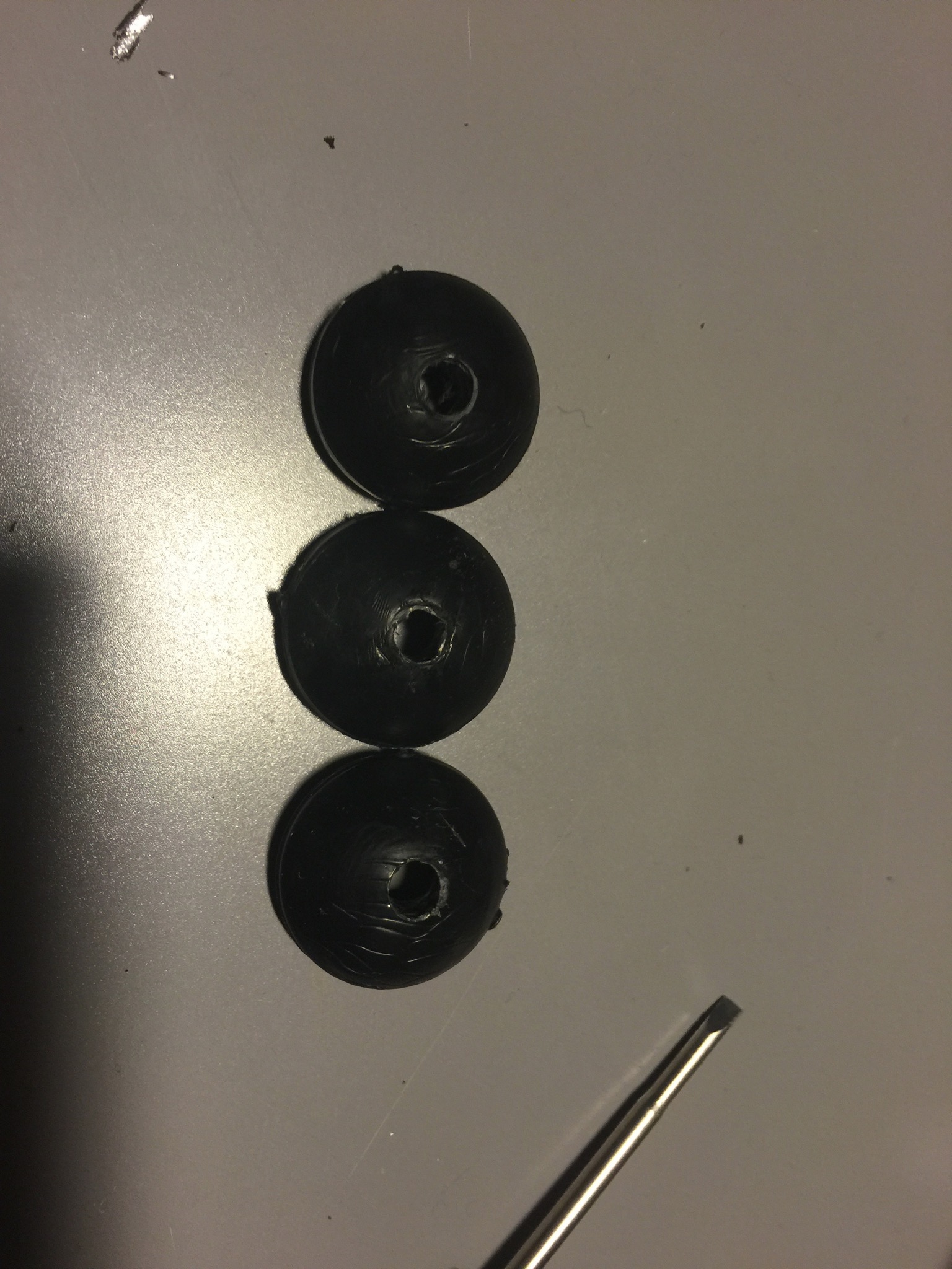
With the holes I could now start fitting the crocodile clips: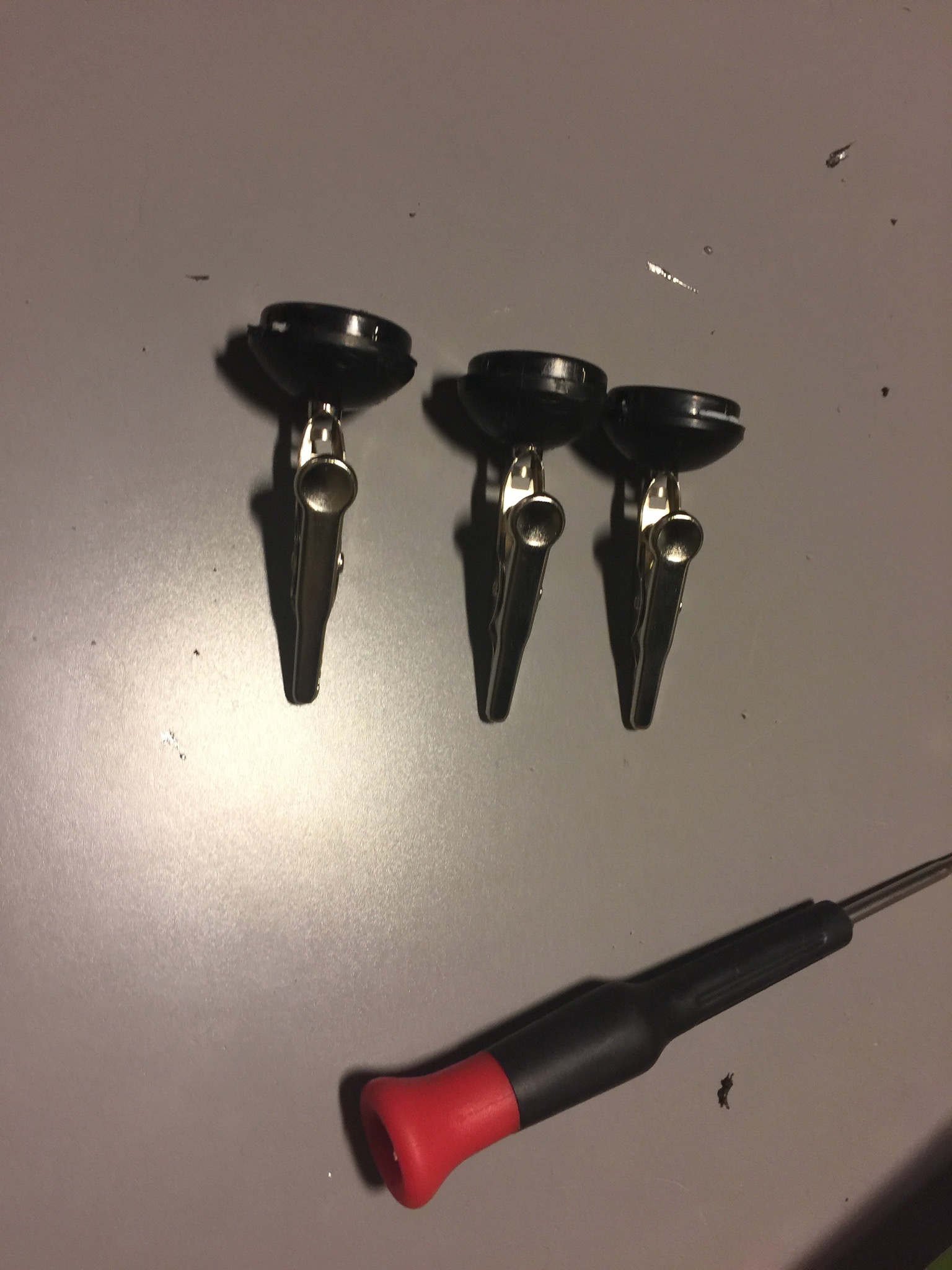
I decided to glue the clips to the hemispheres. This is a decision I might go back on and figure out a better way to attach them to the hemisphere. I’ve thus far had a couple of times they move out - not really a big problem, but still; perfectionism and all :).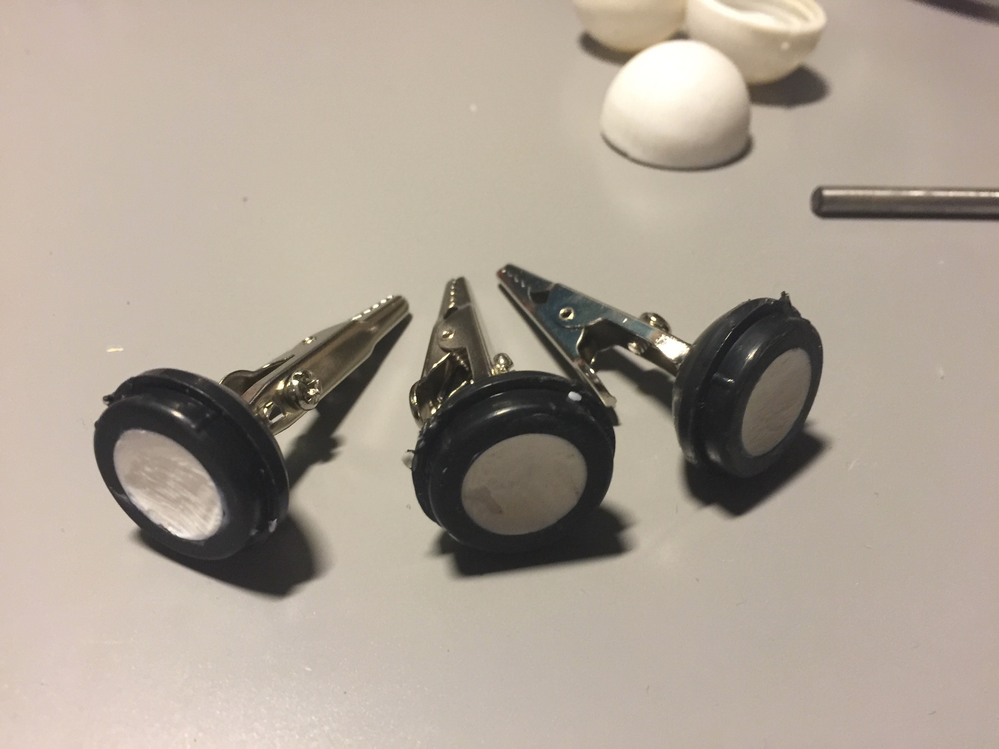
The glue I used is a typical building bond: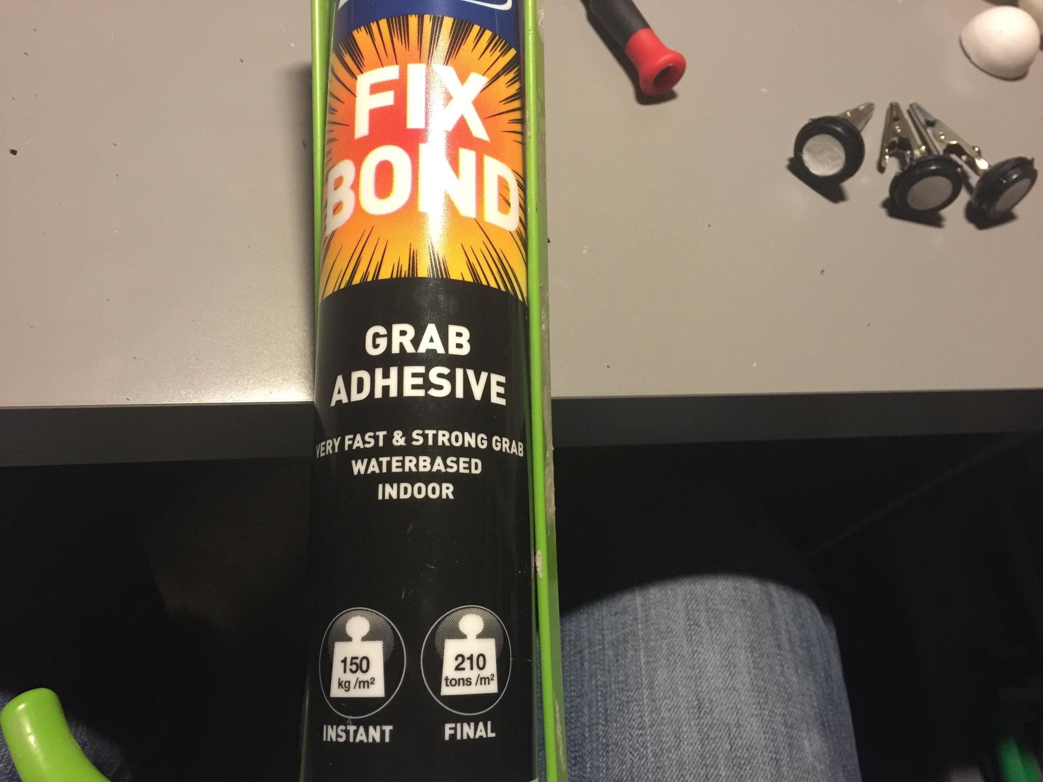
My idea was to have a stone base - heavy enough to not move around when I am working. I had a particular look in mind and wanted to frame the stone. I decided to go with varnished oak, which gives a look I’m quite fond of.
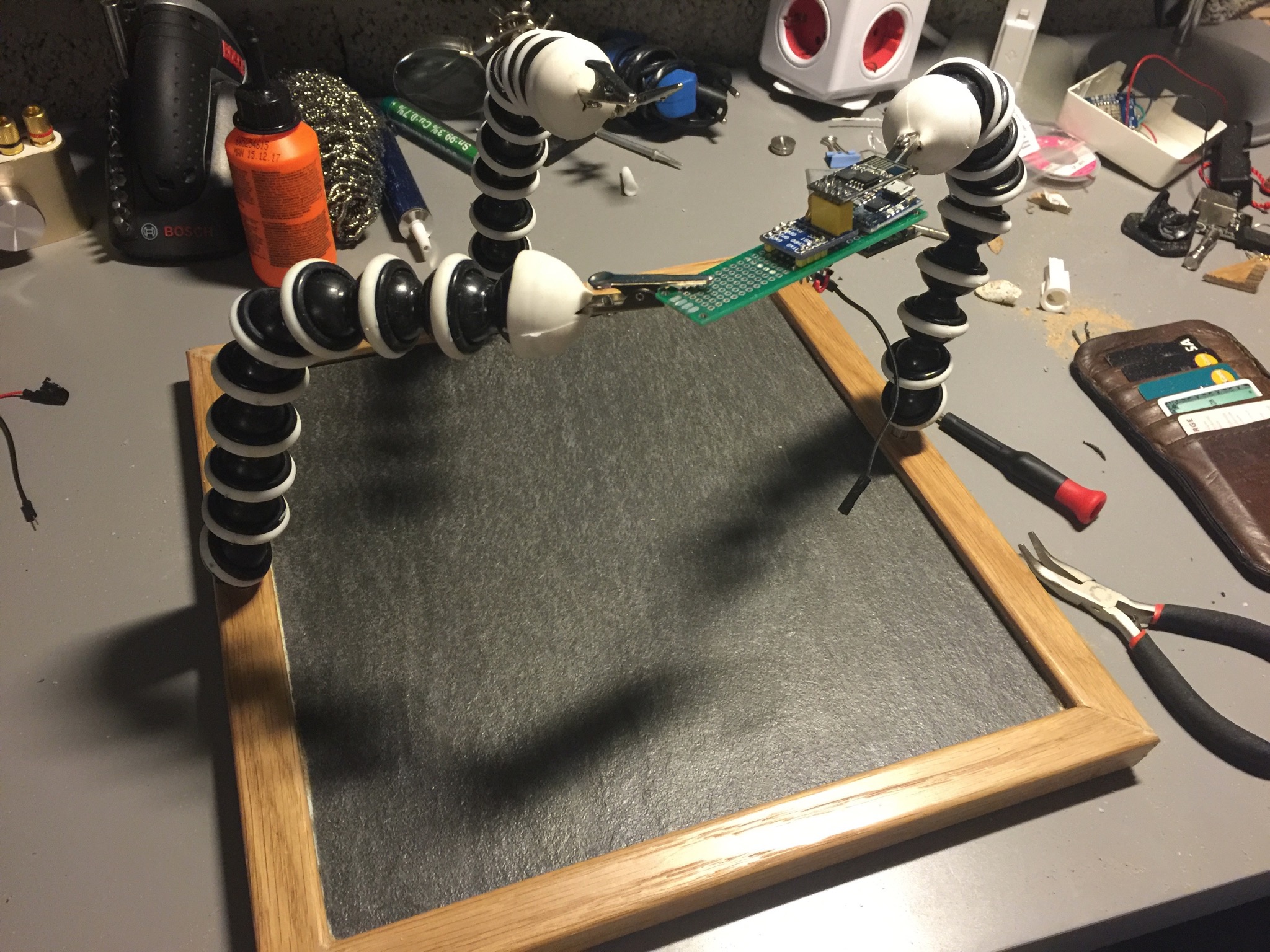
On three of the sides I fitted the arms. I decided to go with stands from a prototyping board I had been using and put the arms on these. First I needed to drill holes for these and an inset for them to fit in.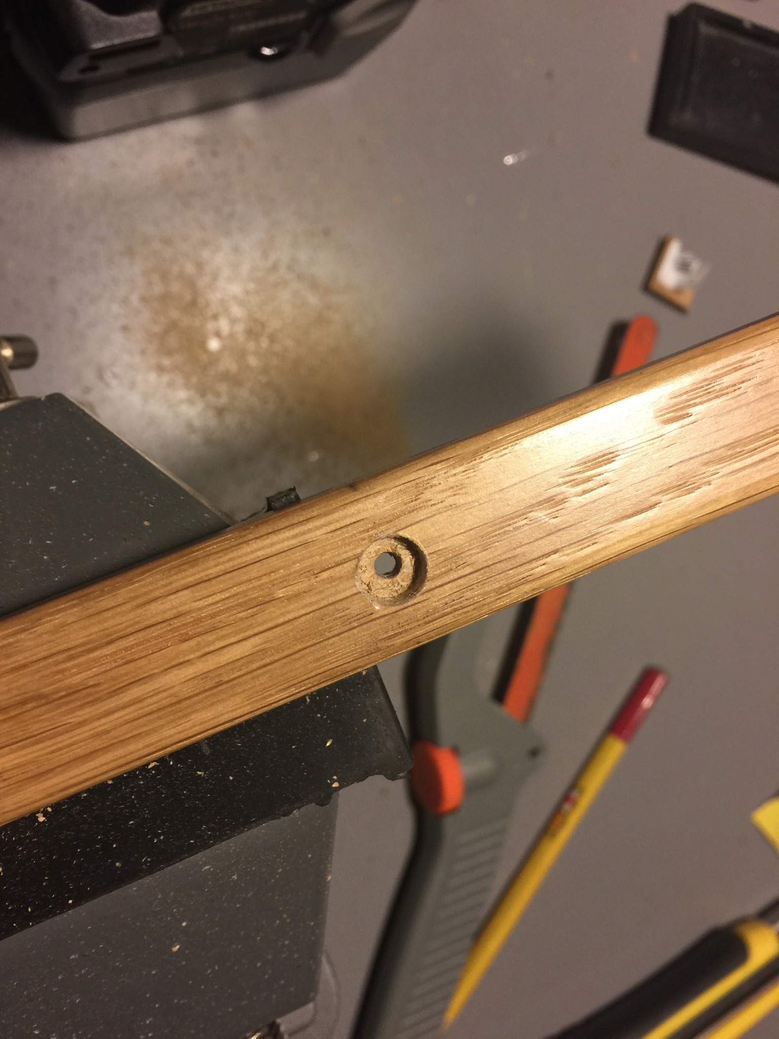
This is how they fit in the inset.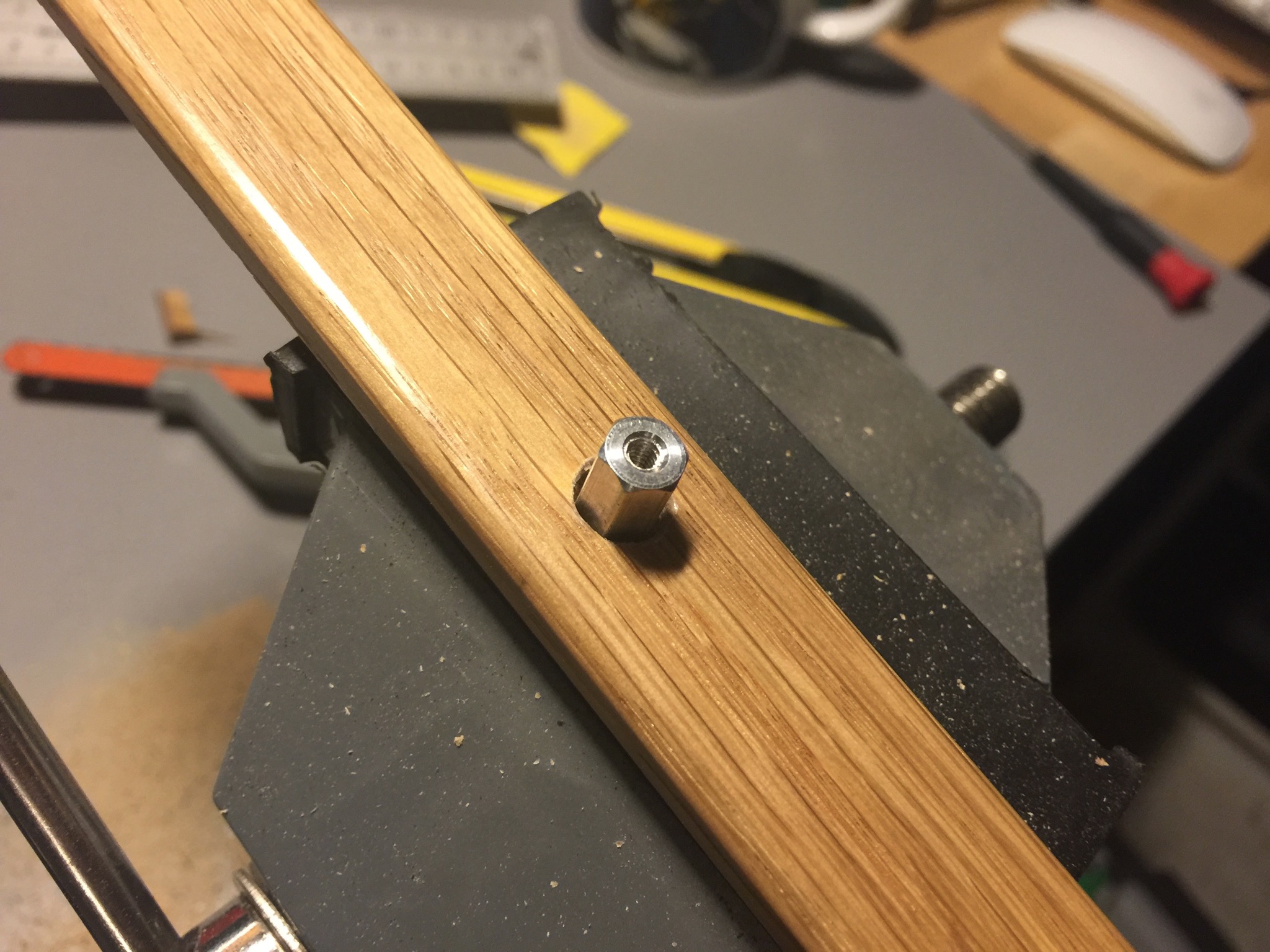
On the flipside I just put a nut on it.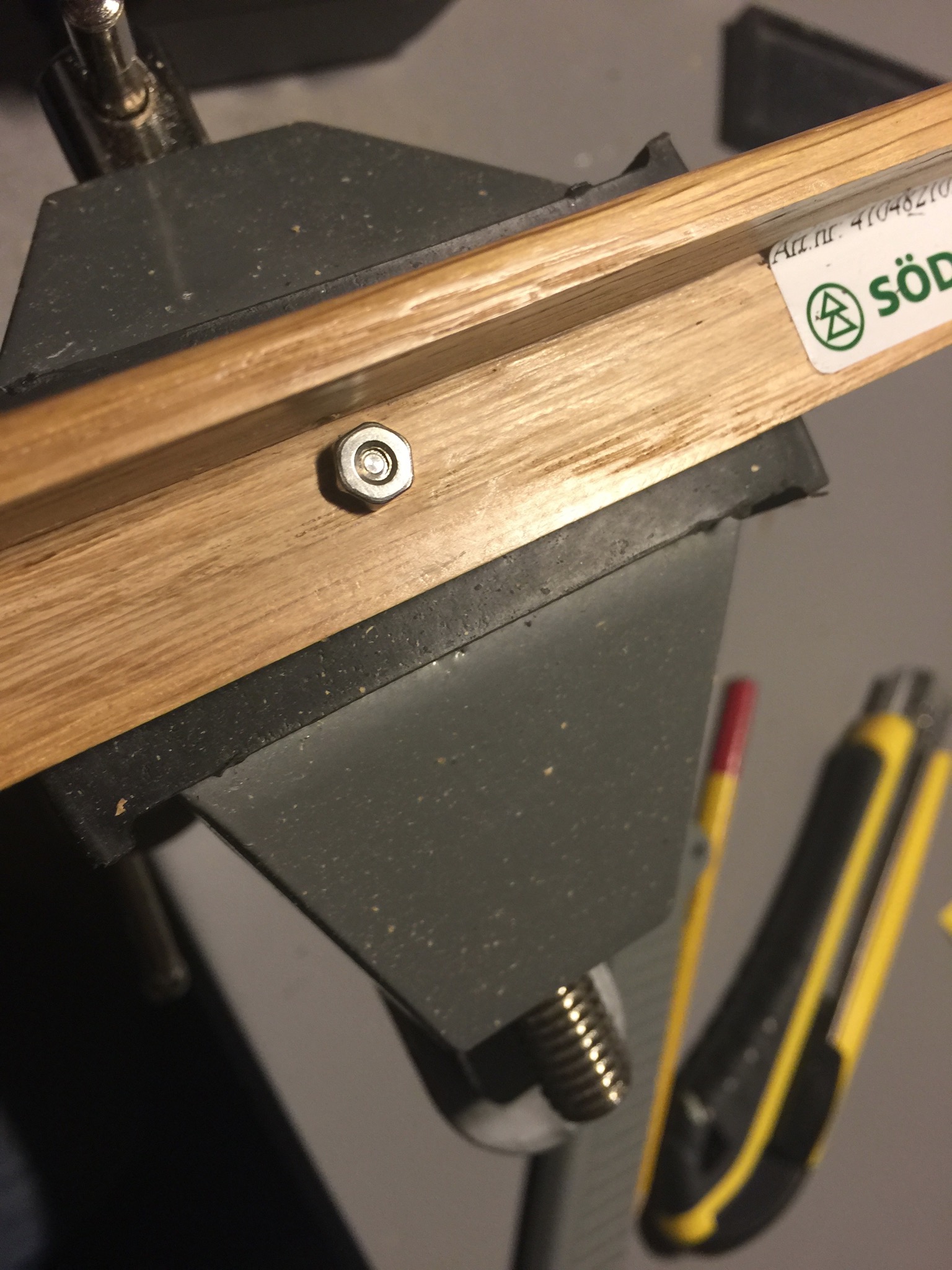
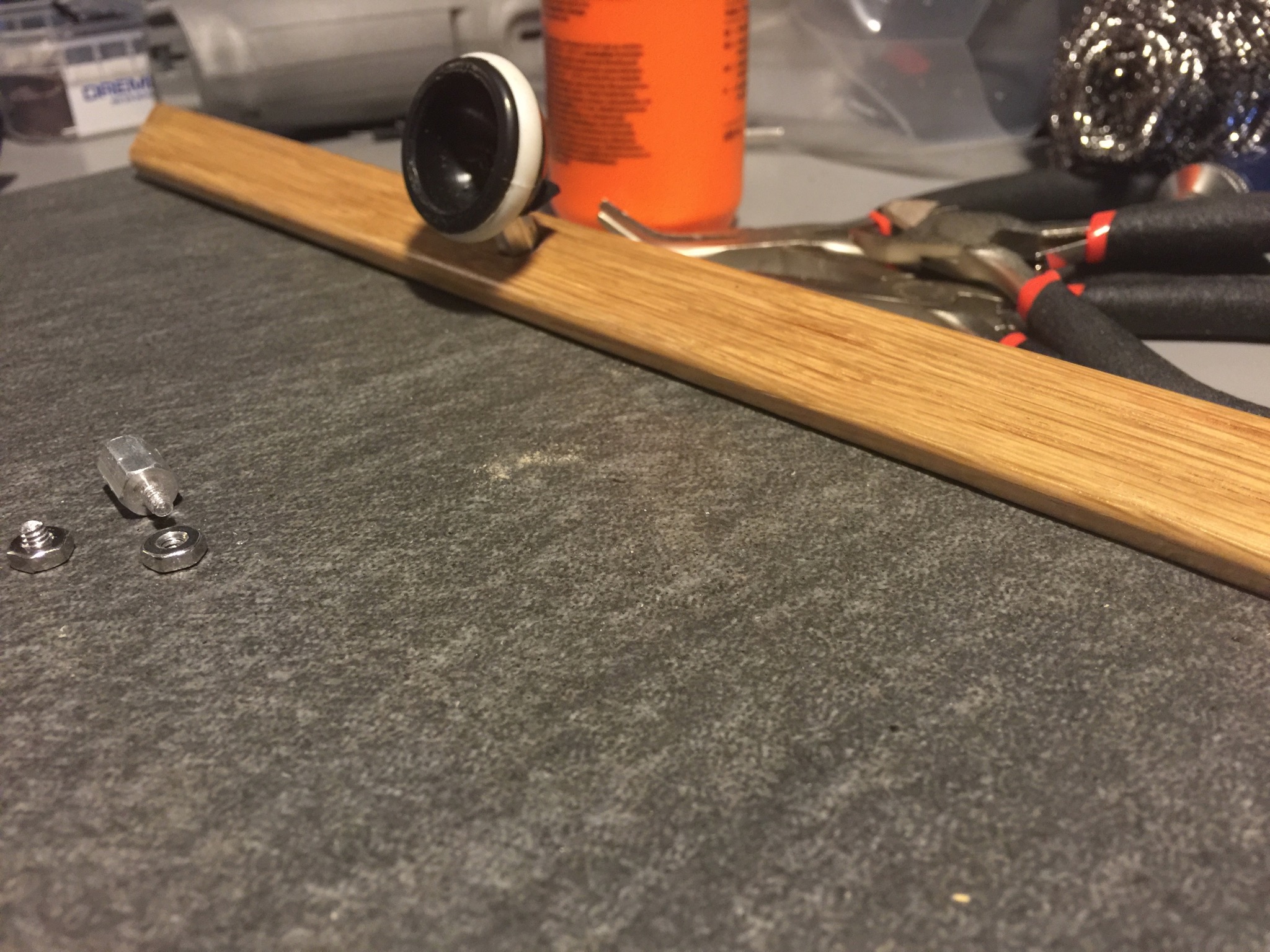
I then drilled a hole in the opposite hemisphere of the leg, the one that was glued to the base. This will then be mounted on top of the stand and attached with a screw going through.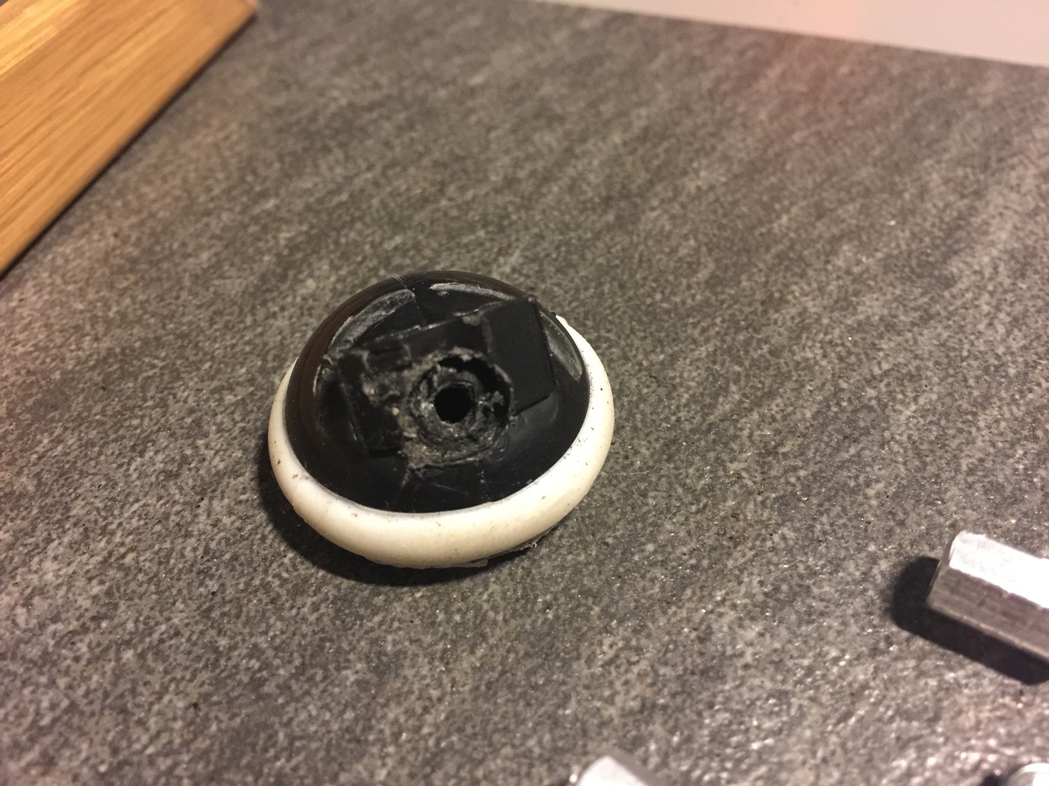
With this in place you can attach a leg and get a general feel. On the picture you’ll see the stone I picked. It is in fact a regular cheramic tile with a specific stony look. This one I got for free at a local tile store. Turns out they hand out tiles for free for the purpose of sampling at home. 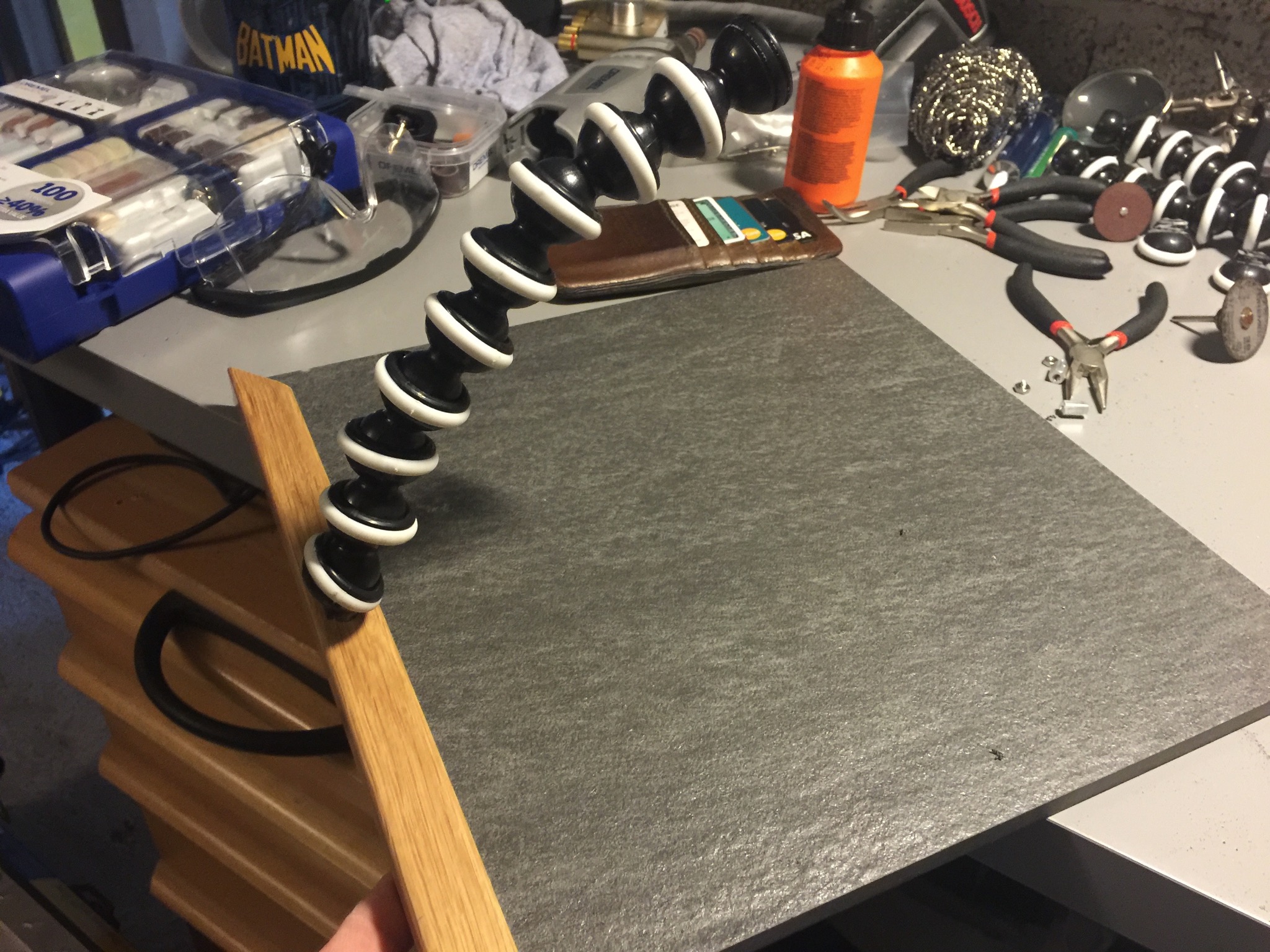
The last piece of the pusle is then to put together the frame and glue it all together. I decided on gluing it all with the same adhesive as mentioned earlier. Its not going to move around all that much, so my theory is that its more than good enough.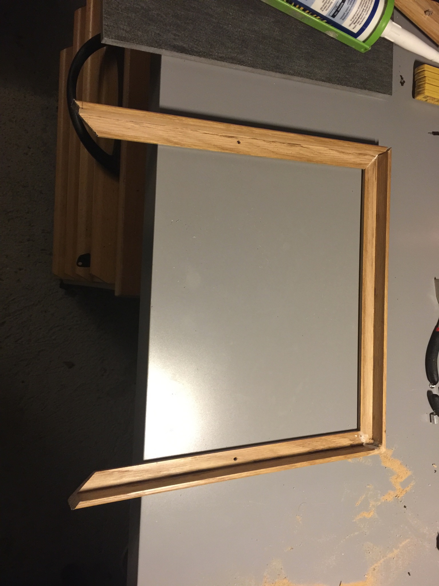
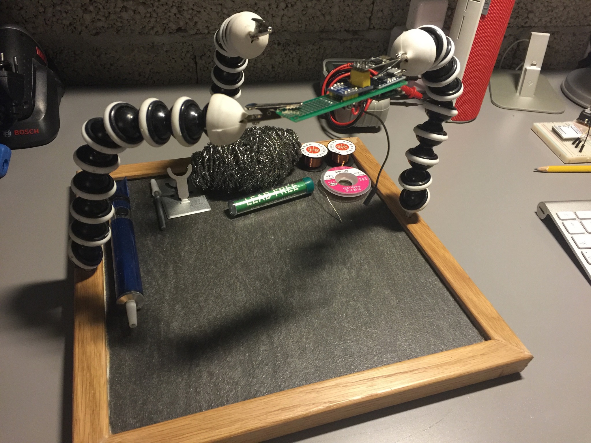
The end result
Next step
This is the first step of this - just to cover my most immediate needs; helping hands. I do however want to expand on it. For instance, adding compartments in front for all the consumables (soldering tin++), cleaning wool - but also a holder for the soldering pen that I use. I’ve also contemplated buying a more advanced soldering pen with a base for regulating the temperature and have looked at a couple that could easily fit in my build. Stay tuned - don’t know when though.. :)